 |
|
|
|
 |
 |
|
 |
| |
Synchronous Motors
 |
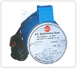
Dec Reversible A.C. Syn. motors are ungeared low Speed 60RPM @ 50 Hz .& offering large torque from 10kg/cm to 40 kg/cm.The motors consist of 3 lead two phase woud stator & permanent magnet rotor.
Features
- Instant start , stop & reversible
- Low speed 60 RPM @ 50 Hz
- Torque From 10 Kg.cm to 40 kg. cm (models).
|
Characteristics
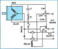
| 1. A.C Operation : Motor can be diretectly connected to 220 V; 50 Hz , Supply along with factory supplied RC network in series with one of stator winding.Change of RC network from one winding
to other results reversal of motor directory.Single pole three position switch can be used for forward, Reverse & Off control as shown in the following diagram. Metel varistor oxide may be used to minimize the switch contact arcing. |
 |
|
2.
Starting : Motor start 1 1/2 Cyckes of its applied frequency & will reach 60 RPM within 5 to 30 ms at 50 Hz .,this motor is ideal to an application which require six 0r more starts per minute. |
| 3. Stalling : Motor will not be overheated if stalled because starting , full load and no load currents are same.However prolonged operation against a solid stop will eventually produce bearing failure due to resultant shaft vibrations. |
| 4. Inertia Limitations : Since the motors are having extremly rapid starting ,there is a limit to the inertia load at which the motor will start from rest. Addition of resilient coupling with app.5 degree of rotational freedom or gearing with backlash between motor & load can increase the permissible inertia handing capability . |
| 5. Phase Shift Network :
The values of RC network have considerable effect on motor performance . They have been chosen by 'DEC' in such a manner that no reverse torque is produced when voltage is applied . RC values should not varied more than 5% so as to enhance smoother starting give quieter operation, maximize torque & improve efficiency OEM application. |
| 6. Stopping & Holding (Braking) : Due to magnetic rotor, these motors decelerate than conventional & stop within 5 degree after turnoff with no external inertia.Application of D.C . Supply to one or both motor windings after removal of A.C . Supply results deceleration time 1/10th to 1/20th those available with conventional motor & the motor shaft is electrically locked after the stop. A typical circuit for applying , stopping & or holding current is shown in the following diagram. |
 |
| 7. Back Driving : These motors act as generators when back driven . Rotating in access of 1400 RPM is not recommended because high voltage can generated . At 1400 RPM or below suitable precautions for protection of pertection of personnal/phase shift capacitor & any other connected circuitry may be necessary when back driving. |
| 8. 60 Hz Operation : These motors may be operated on 60 Hz , but may require a different RC network , the factory must be consulted. Torque rating should be similar to those shown for 50Hz & speed is 72 RPM @ 60 Hz. |
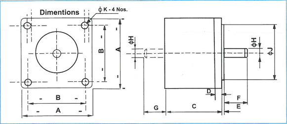
| Dimensional Chart : V 240; 50 Hz 60RPM |
 |
| Note: If extended motor shaft is required, add suffix 'E' in the motor model selected . E.g.:SYN-10E etc. |
| A.C SYN.Motor Models |
Torque Kg-cm |
Dimensions(mm)
|
φK |
Weight Kgs. |
| SYN - 10 |
10 |
108 |
85 |
80 |
7 |
1.5 |
30 |
25 |
10 |
55 |
8 |
3 |
| SYN - 20 |
20 |
108 |
85 |
80 |
7 |
1.5 |
30 |
25 |
10 |
55 |
8 |
3.4 |
| SYN - 30 |
30 |
108 |
85 |
80 |
7 |
1.5 |
30 |
25 |
10 |
55 |
8 |
4.2 |
| SYN - 30 |
30 |
108 |
85 |
80 |
7 |
1.5 |
30 |
25 |
10 |
55 |
8 |
6.0 |
|
|
 |
|
 |
 |
 |
 |
 |
|
|
|
 |

